-
To Provide
the Japan QualitySince its establishment in 1975 SHINKEN has been accumulating knowledge of and experience in ‘Vibration’ for nearly half a century with the world-first productization in 1977 of the Electro-dynamic Multi-axis Vibration Test System (patented in US, UK and Japan - already expired) and development of a variety of customized Vibration Test Systems (some patented) & Vibration-related Products by overcoming many tough difficulties.
-
For Quality-minded Engineers
SHINKEN must always be a challenger for supporting quality-minded engineers with high-quality Vibration Test Systems. To Stand at the forefront of Quality Control and R&D together with our customers, SHINKEN will be challenging for high-quality Vibration Test Systems by putting ourselves at the customer’s positions.
SHINKEN’s Vibration Test Systems
- Multi-Axis Vibration
Test Systems - Single-Axis Vibration
Test Systems - Combined
Environmental
Test Systems - Digital Vibration
Controllers
-
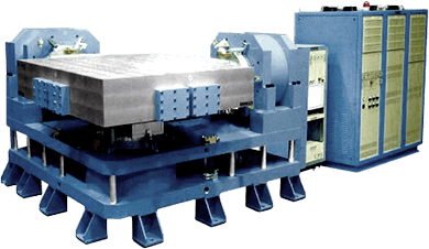
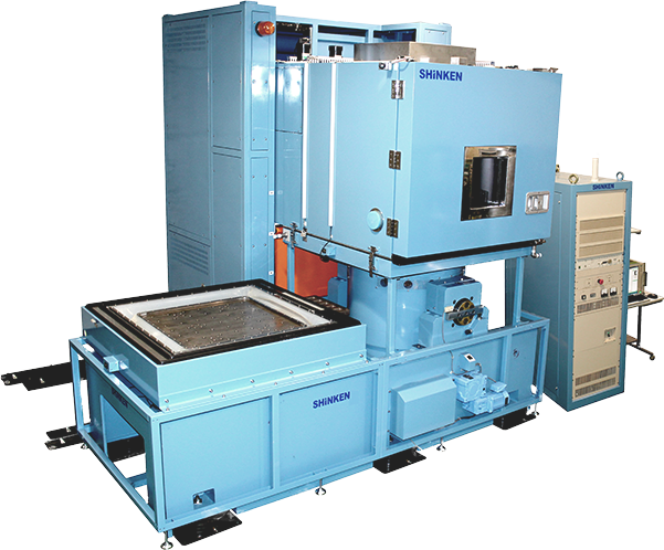
Multi-Axis Vibration Test Systems
In the case of simultaneous excitation, 'More Real-world Vibration' can be simulated. SHINKEN's uniquely-designed Hydrostatic Bearing Coupling Technogym minimizes 'cross-talks (unnecessary leak of vibration from the other axes)' among all the axes and also assures for high waveform fidelity. In addition, in the case of sequential (axis by axis) excitation, time saving and troublesome labor elimination can be achieved as no vertical & horizontal tables handling and also no specimen unloading & loading are needed.
System Series
- 3-axis Simultaneous/ Sequential G-6 Series
- 2-axis Simultaneous/ Sequential G-8 Series
-
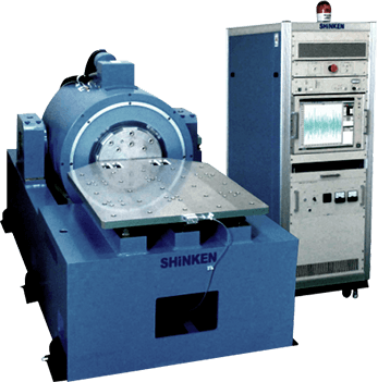
Single-Axis Vibration
Test SystemsIn addition to the accumulated collection of technology for the Multi-axis Vibration Test Systems, SHINKEN has also improved technology for the single-axis Vibration Test Systems typified by the unique Air bearing Guide and Air Suspension Structure (previously patented). SHINKEN can provide any systems meeting the customer's requirements.
System Series
- G-0 Series for General-purpose Tests
- G-9 Series for Transportation Tests
- G-5 Series for Shock & Vibration Tests
- G-3 Series for Large Displacement & Horizontal Vibration Tests
- G-4 Series for High-Frequency Vibration Tests
- G-2 Series for Calibration & Vibration Tests for Small, Light Specimens
-
Combined Environmental
Test SystemsBy combining SHINKEN's Chambers with Vibration Generators, combined environmental tests of vibration, temperature and humidity can be performed with a temperature range of -70 to +180 degrees and a humidity range of 20 to 98%RH. With Chambers and Multi-axis Vibration Generators being combined, more 'Real-world Environment' can be simulated.
System Series
- CS Series
-
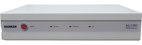
Digital Vibration Controllers
D-59 Series Digital Vibration Controllers, which can be used for not only Electro-dynamic Shakers but also Hydraulic Shakers, are featured by user-friendly usability thus enabling complicated vibration tests to be carried out relatively easily as well as a wide range of applications available with various control functions such as Sine, PSD random, Shock, Mixed Mode, RSTD, Waveform Reproduction and so on. There are 2 types available; B-type: Stand-alone type with PC and TFT built-in and A-type: Control Unit type which can be connected with any Windows 10 PC.
How to Select
the Right System Model
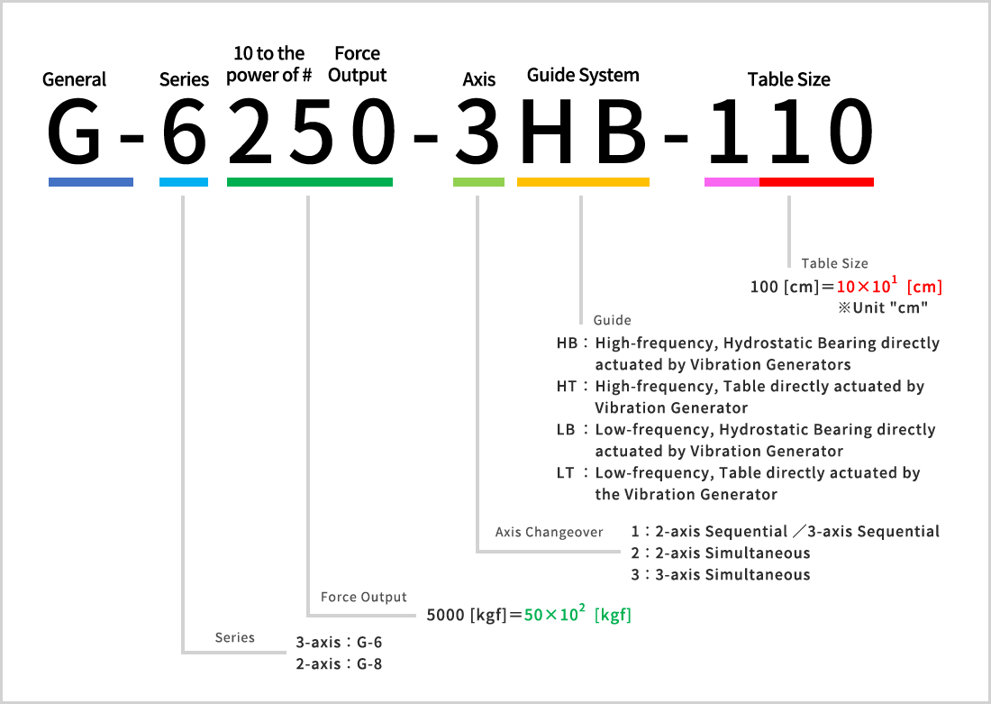
Explanation on System Model
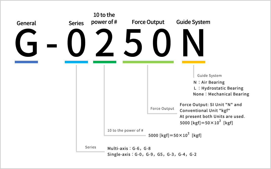
About Multi-Axis Vibration Test Systems
How to calculate required Force Output
For the right System Model selection, the Force Output needed to carry out the required tests is to be calculated. The following formula is used for Force Output calculation:
F=(m₀+M₁+M₂)A
| F: | Force Output | … [N] |
|---|---|---|
| A: | Acceleration | … [m/s²] |
| m₀: | Weight of Bare Table | … [kg] |
| M₁: | Weight of Aux. Table and/or Fixture if any | … [kg] |
| M₂: | Weight of Specimen | … [kg] |
When the Test Acceleration(A) is unknown, the following formula is used. (Only for Sine Tests)
A=2πfV A=(2πf)²D
| f: | Frequency | … [Hz] |
|---|---|---|
| V: | Velocity | … [m/s] |
| D: | Displacement | … [m0-p] |
| A: | Acceleration | … [m/s²] |
About SI Units
The SI Units, recognized internationally at present, are used in this Catalog. The following is a conversion table between the SI Units and the Conventional Units:
| Quantity | Conventional Unit | SI Unit | Conversion Rate |
|---|---|---|---|
| Force | kgf | N | 1kgf=9.8N |
| Acceleration | G | m/s² | 1G=9.8m/s² |
| Velocity | cm/s | m/s | 1cm/s=0.01m/s |
| Frequency | Hz | Hz | - |
| Moment | kgf・m | N・m | 1kgf・m=9.8N・m |
| Pressure | kgf/cm² | Pa | 1kgf/cm²=98kPa |
| Outflow Volume | L/min | m³/s | L/min=(10³/60) m³/sec |
| Heat Volume | kcal | J | 1kcal=4.186kJ |
| Radiate Heat Volume | kcal/h | W | 1kcal/h=1.162W |
| Angle | °(度) | rad | 1°=π・rad/180 |